
| A | |||
|---|---|---|---|
| Alternating Current (AC) | Electron flow that alternates between moving in one direction and then the other. Audio and data are both types of AC. | Unit 1 | |
| AC Riding on DC | AC and DC added together. In most cases that means that enough DC is added so that the AC always stays either above or below zero volts. In that case the electrons are always flowing in the same direction. Uses: When we get to active components (ones which can amplify) you will learn that they can only pass current in one direction. To amplify audio, which is AC, we need to add DC to it, thus getting AC riding on DC. |
Unit 1 | |
| AC+DC | Same as AC Riding on DC (see above). | Unit 1 | |
| Ampere (Amp) | 1 Ampere (Amp) of current means that 6.25 x 10¹⁸ electrons have moved past a point in one second. | Unit 1 | |
| Amplified | Increasing the voltage, current, or power of a signal. | Unit 5 | |
| Anode | The element of a vacuum tube that must be charged most positive for current to flow. Electrons flow from the cathode to the anode inside the tube and the out of the anode to reach outside of the tube. |
Unit 5 |
| B | |||
|---|---|---|---|
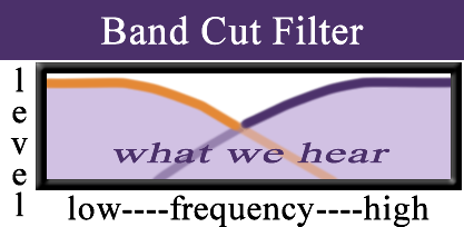
| Band Cut Filter |
|
Unit 4 | |
| Band Pass Filter | 
|
Units 3 & 4 | |
| Biased | When the elements of a component are given the correct relative charges for current to flow, the component is said to be correctly biased. | Unit 5 | |
| Branch | Separate parallel paths in a circuit. | Unit 1 |
| C | |||
|---|---|---|---|
| Capacitance | The ability of a capacitor to store an electrical charge, determined by:
Capacitance is directly proportional to the surface are of the plates and inversely proportional to the separation between them. |
Unit 4 | |
| Capacitive Reactance | The capacitor's equivalent of the resistor's resistance. With a capacitor, however, the value changes depending on the frequency according to: $ \frac {1} {2 \pi FC} $ |
Unit 4 | |
Capacitor
|
Capacitors are another type of passive electronic component. They are made up of two conductive plates with a space in between them. The space is filled with an insulator. This insulator is called the dielectric. | Unit 4 | |
| Capacitors and DC | DC can not pass through a capacitor. | Unit 4 | |
| Cathode | An element in a diode that gives off electrons. The cathode must be more negatively charged than the anode and be heated in order for electrons to flow from it to the anode. | Unit 5 | |
| Cathode Follower | One way of connecting a vacuum tube as an amplifier. The input is connected to the control grid while the output is connected to the cathode. The polarity of the input and output are the same. Also called a common anode amplifier. | Unit 5 | |
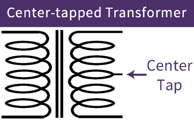
| Center-Tapped Transformer |
|
Unit 5 | |
| Circuit Wizard | Electronic simulation software used in this course and delivered through IUAnyWare. | Unit 1 | |
| Class A Amplifier | Type of amplifier that has current flowing all of the time. While they are not at all efficient but sought after for their audio quality. In a class A amplifier roughly half of the maximum current that will ever flow through the amplifier is flowing when there is no audio present at the input. | Unit 5 | |
| Closed Circuit | Circuit where an electron has a path from where it is now back to that same point. Current can flow in a closed circuit (assuming there is a voltage present). | Unit 1 | |
| Closed Switch | Switch in a position that creates a closed circuit, allowing current to flow. | Unit 1 | |
| Common Anode Amplifier | One way of connecting a vacuum tube as an amplifier. The input is connected to the control grid while the output is connected to the cathode. The polarity of the input and output are the same. Also called a Cathode Follower amplifier. | Unit 5 | |
| Common Cathode Amplifier | One way of connecting a vacuum tube as an amplifier. The input is connected to the control grid while the output is connected to the anode. The polarity of the input and output are opposite. | Unit 5 | |
| Conductor | A material that allows electrical current to flow through it (copper and most metals are good conductors, so are you) | Unit 1 | |
| Connection | A point where two or more components, power sources, or loads are connected together. | Unit 1 | |
| Control Grid | Placed between the cathode and anode, the control grid controls the amount of electron flow from cathode to anode by it's charge. Making the control grid more negative reduces electron flow, while making it more positive increases current flow. It is also often called simply the grid or G1. | Unit 5 | |
| Conventional Current | Simply a different way of thinking about electron flow. It is the same in every way, except that conventional current moves in the opposite direction of electron flow. Conventional current moves from a more positive to a more negative charge. | I← | Unit 1 |
| Current | 1 AMP of current means that 6.25 x 10 18 electrons have moved past a point in one second. | I | Unit 1 |
| Current Divider | A circuit of parallel resistors. The total circuit current is divided up amongst the parallel branches of the circuit. The ratio of current through the branches will be indirectly proportional to the resistance of each branch. The voltage across each branch is the same. You can also think of it as being a circuit where the current through each parallel branch adds up to the total current. |
Unit 2 | |
| Current in a Series Circuit | Current is the same through every component that is connected ina series circuit. | Unit 1 | |
| Current in a Parallel Circuit | Current through the branches in a parallel circuit add up to the total circuit current. | Unit 1 | |
| Current Flow | Simply a different way of thinking about electron flow. It is the same in every way, except that conventional current moves in the opposite direction of electron flow. Conventional current moves from a more positive to a more negative charge. | I← | Unit 1 |
| Current Meter | A current meter determines the amount of current. To do so, the current meter has to be connected in series with the portion of the circuit where you want to measure current flow. All of the electrons in the part of the circuit where you want to measure current flow must go through the current meter. | Unit 1 | |
| Cutoff | When no less current can be made to flow, no matter how much more negative the control grid is made, the tube is said to be in cutoff. | Unit 5 |
| D | |||
|---|---|---|---|
| Decibel |
A logarithmic way to define values. This is used a great deal with audio as it emulates the way that human beings hear. These are often used to reference replationship to a reference value but can also be used to relate any two values of the same type. For power or sound pressure: $20 \log (\frac {X_2}{X_1})$ |
dB | Unit 4 |
| Dielectric | The insulation used between the plates of a capacitor, often used to describe the type of capacitor. What the dielectric is made of will affect the capacitance. | Unit 4 | |
| Diode | Vacuum tube with two elements; the anode and the cathode. | Unit 5 | |
| Direct Current (DC) | Type of electricity where current is always moving in the same direction. | Unit 1 | |
| DC Voltage Sources | Voltage source that creates DC. | Unit 1 | |
| Drop | Voltage used up by a component. Voltage drop is measured across a component. | Unit 1 | |
| DPDT: Double Pole Double Throw |

Double Pole Double Throw: This switch type is two SPDT switches that remain electrically separate but are linked mechanically. This means that when the user physically moves the switch, both electrically seprate switches will change. |
Unit 1 | |
| DPST: Double Pole Single Throw |

|
Unit 1 |
| E | |||
|---|---|---|---|
| Electrical Isolation | Transformers are often used for electrical isolation. There is no electrical connection between the primary and secondary of a transformer, only a magnetic one. This can be used be saftey or to reduce noise caused by connecting two devices. | Unit 3 | |
| Electron |  A subatomic particle with a negative charge. Electrons are the basis for electricity. Because electrons have a negative charge they are attracted to more positive charges and repelled by more negative charges. A subatomic particle with a negative charge. Electrons are the basis for electricity. Because electrons have a negative charge they are attracted to more positive charges and repelled by more negative charges. |
Unit 1 | |
| Electron Flow | Simply a different way of thinking about current flow. It is the same in every way, except that electron flow moves in the opposite direction of conventional current. Electron flow moves from a more negative to a more positive charge. | e→ | Unit 1 |
| Equivalent Circuits | Circuits that contain components that have reactance (inductors and capacitors) can be re-drawn as equivalent circuits that contain resistors in place of the indcutors and capacitors. An equivalent circuit will have values chosen for a single frequency. | Unit 4 |
| F | |||
|---|---|---|---|
| Farad | Unit in which capacitance is measured. Named after physicist Michael Farady. A farad capacitor, when charged with one coulomb of electrical energy will have one volt across it. A coulomb is equal to the amount of charge (electrons) produced by a current of one ampere (A) flowing for one second. | F | Unit 4 |
| Frequency | Frequency is given in Hertz(Hz), which is the number of cycles that are completed per second. Frequency = 1/period (given in seconds) | F | Unit 1 |
| Full Wave Rectifier |

|
Unit 5 |
| G | |||
|---|---|---|---|
| Ground |
Ground is a point in a circuit that is idenified as 0V. (as we connect circuits in later Units, this definition will be expanded)  |
Unit 1 |
| H | |||
|---|---|---|---|
| Half Wave Rectifier |

|
Unit 5 | |
| Henries | Unit for measuring inductance. Named after Joseph Henry, an American scientist known for discovery electromagnetic induction independantly but at about the same time as Michael Farady. | H | Unit 3 |
| Hertz | The units in which frequency is defined. A one hertz waveform completes a cycle in one second. | Hz | Unit 1 |
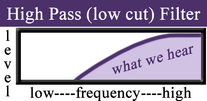
| High Pass Filter |
|
Units 3 & 4 |
| I | |||
|---|---|---|---|
| Impedance Conversion | Changing impedance of something so that correct voltage, current, or power transfer occurs. | Unit 3 | |
| Inductance | Property where current through a conductor "induces" a voltage both in itself and in nearby conductors. | L | Unit 3 |
| Inductive Reactance | The inductor's equivalent of the resistor's resistance. With an inductor, however, the value changes depending on the frequency according to: $2 \pi LC $ |
XL | Unit 3 |
Inductor
|
An inductor is electrically the opposite if a capacitor. It works against changes in voltage. The higher the frequency going into an inductor, the harder it is to get through. Inductance is measured in Henries (i.e. 2.0mH).
 How do Inductors work?
 Current flowing through the coil induces a magnetic field. This magnetic field lags slightly behind the current. (You can also create an electrical current in a coil of wire by adding a magnetic field to it.) Since the magnetic field created by an electrical current lags behind the current, it will stay the same if the current changes. That magnetic field created by the current flow then works against any changes in new current flow. The quicker these changes (higher frequencies) the more the magnetic field works against the current flow. What are some uses for Inductors?Inductors are used in filters to get rid of high frequencies. Passive speaker crossovers and ripple filtering on power supplies are common examples. Since inductors are much more expensive than most passive components you may not see them very often. |
Unit 3 | |
| Inductor Filters | 1) Inductors allow lower frequencies to pass easier than higher frequencies. OR, the higher the frequency, the larger the Reactance of an inductor (which means it drops a larger voltage). 2) The larger the inductance/the larger the wavelength (lower the Frequency) that will be blocked. 
|
Unit 3 | |
| Inductors in Parallel | When connected in parallel, inductor values are added using the inverse rule.


|
Unit 3 | |
| Inductors in Series | When connected in series, inductor values are simply added to find the total inductance.


|
Unit 3 | |
| Insulator | A material that does not allow an electrical current to flow through it (plastic and air are both insulators). | Unit 1 | |
| Inverse Rule | Rule used for adding resistors and inductors when they are connected in parallel and capacitors when they are connected in series. $ \frac {1}{R_{total}} = \frac {1}{R_1} + \frac {1}{R_2} + \frac {1}{R_3} ..... $ |
Units 2,3, & 4 |
| J |
|---|
| K |
|---|
| L | |||
|---|---|---|---|
| Load | The component or components that are using up the electricity. | Unit 1 | |
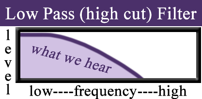
| Low Pass Filter |
|
Units 3 & 4 |
| M | |||
|---|---|---|---|
| mA or Milliampere | The milliamp, whic is .001A, is used more commonly than Amp, because an Amp is a very large amount of current. | Unit 1 | |
| Microfarad | Units most commonly used to measure capacitance. A microfarad is 10-6 of a farad. | µF | Unit 4 |
| N | |||
|---|---|---|---|
| Nanofarad | Unit used to measure capacitance. A nanofarad is 10-9 of a farad. | nF | Unit 4 |
| O | |||
|---|---|---|---|
| Octave | An octave is a musical interval. A frequency that is an octave above would be twice the frequency. | 8VA | Unit 4 |
| Ohms | Units in which resistance is measured. | R | Unit 2 |
| Ohm's Law | $ V = IR $ | Unit 2 | |
| Open Circuit | If there is an open circuit, then it is not possible for the electrons to move. | Unit 1 | |
| Open Switch | Switch in a position that does not allow current to flow. | Unit 1 | |
| Oscilloscope | A voltmeter with two connections per channel, that allows one to see the waveform as it changes over time. They create an image on an X/Y axis where X (left to right) represents change over time and Y (top to bottom) represents Voltage. | Unit 1 |
| P | |||
|---|---|---|---|
| Parallel Circuits | Voltage: The voltage drop across components in a parallel circuit is the same as all other components and the total circuit voltage. Current: The current through components in parallel will add up to the total circuit current. Current through each component will be proportional to its resistance (or impedance). |
Unit 1 | |
| Peak Voltage | A way of describing an AC voltage. Simply the voltage at the highest point of the wave. $ V_{pk}=1.414(V_{rms})$ |
Vpk | Unit 1 |
| Peak to Peak Voltage | A way of describing an AC voltage. The difference between the most positive point of the wave and the most negative point of the wave. In a sine wave, twice the Vpk. | Vpk-pk | Unit 1 |
| Period | Period is the time it takes for a single cycle of an AC wave to complete. | Unit 1 | |
| Phase | The timing of different signals and how they replate to each other. | Unit 3 | |
| Picofarad | Unit used to commonly measure capacitance. A picofarad is 10-12 of a farad. | pF | Unit 4 |
| Potentiometers |

|
Unit 2 | |
| Power | The rate at which work is done. Power is measured in units called Watts. The formula for power is simply voltage multiplied by current, $ P = VI$. | P | Unit 1 |
| Q |
|---|
| R | |||
|---|---|---|---|
| Reactance | The equivalent of a resistor's resistance. With reactance, however, the value changes depending on the frequency. | Unit 3 | |
| Rectification | Rectification is used to convert AC into DC. | Unit 5 | |
| Resistance | Term for the property of "impeding" current flow. A material that is a conductor will have low resistance while an insulator will have very high resistance. The better the conductor, the lower the resistance. The better the insulator, the higher the resistance. | Unit 2 | |
| Resistor
|
An electrical component used because it has a specific resistance. Resistors use color coded stripes to indicate their value and tolerance. | Unit 2 | |
| Resistor Color Code |


See Unit 2, page 2 for details. |
Unit 2 | |
| Resistor Tolerance |

|
Unit 2 | |
| Resistors in Series | The total resistance of resistors in series is found with simple addition of their values. (R1 + R2 + R3 + ...)

|
Unit 2 | |
| Resistors in Parallel | The total resistance of resistors in parallel is found by using the following formula: (1/R1 + 1/R2 + 1/R3 +...=1/RTOTAL)

|
Unit 2 |
| S | |||
|---|---|---|---|
| Saturation | When no more current can be made to flow, no matter how much more positive the control grid is made, the tube is said to be in cutoff. | Unit 5 | |
| Schematic | A visual representation of the electronic circuit. You can think of it as a map. That map shows:
|
Unit 1 | |
| Series | If two components are connected in series an electron flowing through one component must flow through the other component. If there is any way for the electron to flow through one component and not the other, then the two components cannot be said to be connected in series. |
Unit 1 | |
| Series Circuits | Voltage: The voltage drop of components in series will add up to the total circuit voltage. Each component will drop a voltage proportional to its resistance (or impedance). Current: The current through any component in a series circuit is the same as all other components and the circuit current. |
Unit 1 | |
| Sine Wave | Most common form of A.C. A geometric waveform that oscillates periodically, and is defined by the function y = sin x. In other words, it is an s-shaped, smooth wave that oscillates above and below zero.

|
Unit 1 | |
| SPST: Single Pole Single Throw |

|
Unit 1 | |
| SPDT: Single Pole Double Throw |

|
Unit 1 | |
| Square Wave |

|
Unit 1 | |
| Switch | Switches either allow or do not allow electrons (current) to flow. They do this by creating an open (current can't flow) or closed (current can flow) circuit. | Unit 1 |
| T | |||
|---|---|---|---|
| Test Points | Place to connect in a circuit to make a measurement. Tupically this is referenced to GND. | Unit 2 | |
| Tolerance | Tolerance indicates how close + or - the actual value of the resistor is to its stated value. | Unit 2 | |
| Triangle Wave |

|
Unit 1 | |
| Transformer
|
If you wind two inductors (called windings)together and put a current through one, it will induce a magnetic field in the other. This magnetic field then induces an electrical current in the other. You have created a transformer. One of the windings is called the Primary, the other the Secondary. Power must be equal between the primary and secondary. |
Unit 3 | |
| Triode | The most common type of tube is the Triode. The triode adds a third element called theControl Grid. When an AC signal is placed on the grid, current will follow that AC voltage. That makes an amplifier! Triodes are Transconductance Amplifiers. That means that a change in voltage at the input produces a change in current at the output. |
Unit 5 | |
| Turns Ratio | Ratio of the number of windings of the primary and secondary in a tansformer. The voltage ratio is the same as the turns ratio. | Unit 3 |
| U |
|---|
| V | |||
|---|---|---|---|
| Vpk | A way of describing an AC voltage. Simply the voltage at the highest point of the wave. $ V_{pk}=1.414(V_{rms}) $ |
Unit 1 | |
| Vpk-pk | A way of describing an AC voltage. The difference between the most positive point of the wave and the most negative point of the wave. In a sine wave, twice the Vpk. | Unit 1 | |
| Vrms | The most common way to describe an AC voltage. Relates the AC voltage to what a comparable DC voltage would be. $ V_{rms}=0.707(V_{pk}) $ $ V_{pk} = 1.414(V_{rms}) $ |
Unit 1 | |
| Vacuum Tube | Electronic device that controls current through a vacuum in a selaed container. | Unit 5 | |
| Valence Electrons | Electrons in the outer orbit. The fewer valence electrons, the more likely the atom is to have (and accept) free electrons, which means conduct electricity. | Unit 1 | |
| Voltage | Term used to designate electrical pressure or force that causes current to flow. Also known as "potential." | V | Unit 1 |
| Voltage Across | The difference in voltage from one end of an electrical component or circuit to the other. Also called "voltage drop". It is the amount of voltage "used up" by the component. When measuring, the two ends of the Voltmeter should be connected to either end of the component. | Unit 1 | |
| Voltage At | The difference in voltage between the given point and Ground (GND). When measuring, the red lead of the voltmeter should be connected to the point and the black lead to Ground. | Unit 1 | |
| Voltage Conversion | Either increasing or decreasing AC voltage through the use of a transformer. Power will remain the same so that if you double to voltage there will he half the current after conversion compared to that before. | Unit 3 | |
| Voltage Divider | When multiple resistors are connected in series with a voltage at one end (either positive or negative, AC or DC) and a different voltage at the other end (often ground) you have a voltage divider. The total voltage is divided up among the resistors. This creates different voltages at the point between the resistors. | Unit 2 | |
| Voltage Drop | The difference in voltage from one end of an electrical component or circuit to the other. Also called "voltage across". It is the amount of voltage "used up" by the component. When measuring, the two ends of the Voltmeter should be connected to either end of the component. | Unit 1 | |
| Voltage in Series Circuits | The voltages dropped by components connected in series will add up to the total voltage of the circuit. | Unit 1 | |
| Voltage in Parallel Circuits | In a parallel circuit each branch of the circuit drops the entire voltage applied by the source. | Unit 1 |
| W | |||
|---|---|---|---|
| Watts | The units in which power is measured. |
Unit 1 | |
| Waveform | The pattern of the signal. | Unit 1 | |
| Wavelength | The physical length of the AC wave. Wavelength = Speed / Frequency (speed of sound is 1128 feet per second) |
Λ | Unit 1 |
| X |
|---|
| Y |
|---|
| Z |
|---|